Small Decentralized Hydropower Program National ... - Cd3wd.com
Small Decentralized Hydropower Program National ... - Cd3wd.com
Small Decentralized Hydropower Program National ... - Cd3wd.com

You also want an ePaper? Increase the reach of your titles
YUMPU automatically turns print PDFs into web optimized ePapers that Google loves.
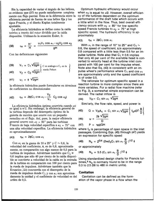
Sin lb; capaeidad de variar el gngulo de las helices,<br />
es evidente que (37) no puede satisfacerse l:ompletamente<br />
con flujo par&l. Esta es la diferencia entre la<br />
eficiencia partial de fuerza de una h&lice fija y 10s<br />
tipos Francis, y el disefio Kaplan totalmente<br />
ajustable.<br />
La eficiencia hidraulica se define <strong>com</strong>a la caida<br />
+n&+o C-v”. .d 2 t,rav& de] rotor $,vidido par 1% cai&<br />
disponible. Utilizando la ecuacion Euler, 5:<br />
(38)<br />
U’V’ cos a, -u2”2 cos a2<br />
‘1H = ; = -<br />
. . CM<br />
Con las definiciones siguientes<br />
(40)<br />
V2 = C2 v2gH<br />
(41) ul = + d2gH<br />
C es aniiloga a C, en la<br />
rueda Pelton<br />
1<br />
Optimum hydraulic efficiency would occur<br />
when a2 is equal to n/2. However, overall efficien-<br />
cy of the turbines dependent on the optimum<br />
performance of the draft tube which occurs with<br />
a little whirl in the flow. Thus, best overall effi-<br />
ciency occurs with a2 = 85” for low specific<br />
speed Francis turbines to 42 = 75” at high<br />
(43) t)H = 2QCj cos a,<br />
With ~~ in the range of IO” to 25” and Cl m<br />
0.6, the speed of coefficient, +.is approximately<br />
0.8 <strong>com</strong>pared with a little less than 0.5 for an impulse<br />
turbine. Note also that Cy g 0.6 implies<br />
that only 40 per cent of the available head is converted<br />
to velocity head at the turbine inlet <strong>com</strong>pared<br />
with 100 per cent for the impulse wheel.<br />
Note also that Eq. (43) is consistent with an impulse<br />
wheel’s performance where Cl and cos al<br />
are approximately<br />
is of order 0.5.<br />
unity and the speed coefficient<br />
The rationale for optimum specific speed in a<br />
la eficiencia hidraulica puede formularse en terminos<br />
de coeficientes no dimensionales<br />
reaction turbine is more <strong>com</strong>plex since there are<br />
more variables. For a radiai flow machine (refer<br />
to Fig. 3), a somewhat simple expression can be<br />
(42)<br />
“a<br />
‘1H = 24~~ ~3s al -2<br />
“1<br />
c2 cos a2)<br />
derived. The radial inflow is<br />
(44) VR= Cl sin al d2gH<br />
La eficiencia hidraulica optima ocurritia cuando a2<br />
es igual a n/:2. Sin embargo, la eficiencia general de<br />
la turbina depende de1 desempeno optima de la<br />
galeria de suction que ocurre con un pequefio<br />
remolino en el flujo. Asi, pues, la mejor eficiencia<br />
general ocurre con ti2 = 85” para las turbinas<br />
Simil’arly, the flow rate, speed, and power is<br />
(45) Q = VPAc = (2.1 sin al G fbrrD2 i<br />
1<br />
24 d&i7<br />
(46) VJ = D<br />
I<br />
Francis de baja velocidad especifica a ag = 75” con (47) P = qegQH<br />
una alta velocidad especifica. La eficiencia hidraulica where fb is percentage of open space in the inlet<br />
es aproximadamente passages. Combining Eqs. (45) through (47) yields<br />
an expression for specific speed<br />
(43) tlH = 24cl cos al<br />
Con al en la ga.ma de 10 a 25” y C m 0,6, la<br />
velocidad de1 coeficiente, 4, es de 0,8, aproximada-<br />
mente, en <strong>com</strong>paracion con algo menos de 0,5 para la<br />
turbina de impulsos. Adviertase tambien que Cl s<br />
0,6 implica que solo 40 por ciento de la caida disponi-<br />
ble se convierte a velocidad de la caida en la entrada<br />
de la turbina en <strong>com</strong>paracion con 100 por ciento para<br />
la rueda de impulsos. Adviertase tambien que la<br />
Ecuacion (45) concuerda con el disempeno de la<br />
rueda de impulsos donde Cl y cos ai son aproxima-<br />
damente la unidad y el coeficiente de velocidad es de1<br />
orden de 0,5.<br />
139<br />
(48) N, = $I4 (2X?jfbC1 Sin al g )1’2 4<br />
or approximately<br />
(49) N, = 5.5 (Cl sin al i )A@ 4<br />
Using standardized design charts for Francis tur-<br />
bines,4 Ns is normally found to be in the range<br />
0.3 to 2.5 (58 to 480 in metric units).<br />
Cavitation<br />
Cavitation can be defined as the form-<br />
ation of the vapor phase in a flow when the
![Mum, int. [man] - Cd3wd.com](https://img.yumpu.com/51564724/1/190x134/mum-int-man-cd3wdcom.jpg?quality=85)