Small Decentralized Hydropower Program National ... - Cd3wd.com
Small Decentralized Hydropower Program National ... - Cd3wd.com
Small Decentralized Hydropower Program National ... - Cd3wd.com

You also want an ePaper? Increase the reach of your titles
YUMPU automatically turns print PDFs into web optimized ePapers that Google loves.
Canal de Toma<br />
CANAL INTAKE<br />
SETTLING<br />
POND s+----\<br />
Acueducto<br />
Ctimara de Salida<br />
AFTERBAY<br />
Toma de Potencia<br />
TRANSMISSION LINE<br />
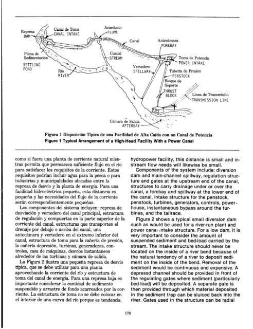
Figura 1 Disposicih Tipica de una Facilidad de Alta Ctida con un Canal de Potencia<br />
Figure 1 Typical Arrangement of a High-Head Facility With a Power Canal<br />
<strong>com</strong>a si fuera una plants de corriente natural mien-<br />
tras permita que permaezca suficiente flujo en el tie<br />
para satisfacer 10s requisitos de la corriente. Estos<br />
requisitos podrian incltir agua para la pesca o para<br />
industrias y municipalidades ubicadas entre la<br />
represa de de&o y la plants de energia. Para una<br />
facilidad hidroelectrica pequena, esta distancia es<br />
pequefia y las necesidades de1 flujo de la corriente<br />
seran correspondientemente pequenas.<br />
Los <strong>com</strong>ponentes de1 sistema incluyen: represa de<br />
desviacion y vertedero de1 canal principal, estructura<br />
de regulacidn y <strong>com</strong>puertas en la parte superior de la<br />
corriente de1 canal, estructuras que transporten el<br />
drenaje por debajo o arriba de1 canal, una<br />
antecamara y vertedero en el extremo inferior de1<br />
canal, estructura de toma para la carieria de presion,<br />
!a carieria depresidn, turbinas, generadores, con-<br />
troles, casa de mkquinas, destios instantaneos<br />
alrededor de las turbinas y camara de salida.<br />
La Figura 2 ilustra una pequena represa de de&o<br />
tipica, que se debe utilizar pars una planta<br />
aprovechando la corriente de1 rfo y estructura de<br />
toma de1 canal de energ3a. Para una represa baja es<br />
importante considerar la cantidad de sedimento<br />
suspendido y arrastre de fondo acarreados por la cor-<br />
riente. La estructura de toma no se debe colocar en<br />
el interior de una curva de1 rio porque es tendencia<br />
170<br />
hydropower facility, this distance is small and in-<br />
stream flow needs will likewise be small.<br />
Components of the system include: diversion<br />
dam and main-channel spillway, regulation struc-<br />
ture and gates at the upstream end of the canal,<br />
structures to carry drainage under or over the<br />
canal, a forebay and spillway at the lower end of<br />
the canal, intake structure for the penstock,<br />
penstock, turbines, generators, controls, power-<br />
house, instantaneous bypass around the tur-<br />
bines, and the tailrace.<br />
Figure 2 shows a typical small diversion dam<br />
such as would be used for a river-run plant and<br />
power canal intake structure. For a low dam, it is<br />
very important to consider the amount of<br />
suspended sediment and bed-load carried by the<br />
stream. The intake structure should never be<br />
located on the inside of a river bend because of<br />
the natural tendency of a river to deposit sedi-<br />
ment on the inside of the bend. Removal of the<br />
sediment would be continuous and expensive. A<br />
depressd channel should be provided in front of<br />
the regulating gates where sediment (particularly<br />
bed-load) will be deposited. A separate gate is<br />
then provided through which material deposited<br />
in the sediment trap can be sluiced back into the<br />
river. Gates used in the structure can be radial

![Mum, int. [man] - Cd3wd.com](https://img.yumpu.com/51564724/1/190x134/mum-int-man-cd3wdcom.jpg?quality=85)