Small Decentralized Hydropower Program National ... - Cd3wd.com
Small Decentralized Hydropower Program National ... - Cd3wd.com
Small Decentralized Hydropower Program National ... - Cd3wd.com

Create successful ePaper yourself
Turn your PDF publications into a flip-book with our unique Google optimized e-Paper software.
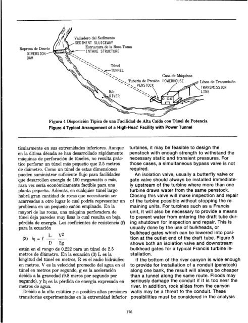
Represa dl; ucj3v1v<br />
DIVERSIONy<br />
CAM<br />
Vaciadero de1 Sediaento<br />
SEDIMENT SLUICEWAY<br />
Estructura de la Bow Toma<br />
INTAKE STRUCTURE<br />
Casa de M5,quinas<br />
Figura 4 Disposicih Tipica de una Facilidad de Alta Caida con The1 de Potencia<br />
Figure 4 Typical Arrangement of a High-Heat! Facility with Power Tunnel<br />
ticularmente en sus extremidades inferiores. Aunque<br />
en la Uima dkada se han desarrollado rapidamente<br />
maquinas de perforaci6n de Wneles, no resulta prac-<br />
tico perforar un tune1 mas pequeno que 2.5 metros<br />
de diametro. Como un tune1 de estas dimensiones<br />
pueden suministrar suficiente flujo para facilidades<br />
que desarrollen energia de 100 megawatts o mas,<br />
rara vez serfa econ6micamente factible para und<br />
planta pequefia. Ademas, en cualquier tine1 largo<br />
habra g-ran cantidad de rotas que necesitaran ser<br />
acarreadas a otro lugar lo cual podtia representar un<br />
problema en un pequeno caricin empinado. En la<br />
mayon’ de las rocas, una maquina perforadora de<br />
tine1 deja paredes muy lisas lo cual resulta en baja<br />
perdida de energia. Los coeficientes de resistencia (f)<br />
para la ecuacih<br />
(3) hl = f & v”<br />
u f4z<br />
est.&n en el rango de 0.222 para un tune1 de 2.5<br />
metros de d%metro. En la ecuaci6n (3) L es la<br />
longitud de1 tine1 en metros, R es el radio hidraulico<br />
en metros. V es la velocidad promedio de1 agua en el<br />
tune1 en metros por Segundo, g es la aceleraci6n<br />
debida a la gravedad (9.8 meros por Segundo por<br />
Segundo), y hl es la p&dida de energfa expresada en<br />
metros de agua.<br />
Debido a la alta estitica y a posibles altas presiones<br />
transitorias experimentadas en la extremidad inferior<br />
Linea de Transmisih<br />
TRANSMISSION<br />
turbines, it may be feasible to design the<br />
penstock with enough strength to withstand the<br />
necessary static and transient pressures. For<br />
those cases, a simultaneous bypass valve is not<br />
required.<br />
An isolation valve, usually a butterfly valve or<br />
gate valve should always be installed immediate-<br />
ly upstream of the turbine where more than one<br />
turbine draws water from the same penstock.<br />
Closing this valve will make inspection and repair<br />
of the turbine possible without stopping the re-<br />
maining units. For turbines such as a Francis<br />
unit, it wiil also be necessary to provide a means<br />
to prevent water from entering the draft tube dur-<br />
ing shutdown for inspection and repair. This is<br />
usually done by the use of bulkheads, or<br />
bulkhead gates which can be lowered into posi-<br />
tion at the outlet end of the draft tube. Figure 5<br />
shows both an isolation valve and downstream<br />
bulkhead gates for a typical Francis turbine in-<br />
stallation.<br />
If the bottom of the river canyon is wide enough<br />
to provide for installation of a conduit (penstock)<br />
along one bank, the result will always be cheaper<br />
than a tunnel along the same route. Floods may<br />
seriously damage the conduit if it is too near the<br />
river. In addition, rock slides from the canyon<br />
walls may be a threat to the conduit. These<br />
possibilities must be considered in the analysis<br />
176
![Mum, int. [man] - Cd3wd.com](https://img.yumpu.com/51564724/1/190x134/mum-int-man-cd3wdcom.jpg?quality=85)