- Page 1 and 2:
SL&A ARCHITECTS A R C H I T E C T U
- Page 3 and 4:
DIVISION 4 - MASONRY Section 04200
- Page 5 and 6:
Section 16740 - Telephone and Data
- Page 8 and 9:
SECTION 00010 - NOTICE TO SUBCONTRA
- Page 10 and 11:
SECTION 00100 - INSTRUCTIONS TO BID
- Page 12 and 13:
A. Prior to signing the contract, t
- Page 14 and 15:
SECTION 00300 - BID FORM TO: Peck O
- Page 16 and 17:
SECTION 00350 - FORMS PART 1 - GENE
- Page 18 and 19:
Utah State Tax Commission Exemption
- Page 20 and 21:
SECTION 00500 - PROJECT SCHEDULES P
- Page 22 and 23:
28. Temporary Field Office, Storage
- Page 24 and 25:
SECTION 00700 - GENERAL CONDITIONS
- Page 26 and 27:
SUPPLEMENTARY GENERAL CONDITIONS Th
- Page 28 and 29:
Irrespective of the requirements as
- Page 30:
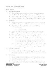
DIVISION 1 - GENERAL REQUIREMENTS S
- Page 33 and 34:
to this project, unless a higher st
- Page 35 and 36:
B. Alternate No. 2 - 80 Mil Single-
- Page 37 and 38:
substantiate quantities. 3. Indicat
- Page 39 and 40:
A. General: Limitations on usage as
- Page 41 and 42:
SEGO LILY ELEMENTARY SCHOOL CLASSRO
- Page 43 and 44:
SEGO LILY ELEMENTARY SCHOOL CLASSRO
- Page 45 and 46:
END OF SECTION 4. Copies of Standar
- Page 47 and 48:
including related specification sec
- Page 49 and 50:
SEGO LILY ELEMENTARY SCHOOL CLASSRO
- Page 51 and 52:
e. Name of supplier. f. Change Orde
- Page 53 and 54:
coincide with submittal of the fina
- Page 55 and 56:
affected by decisions or actions re
- Page 57 and 58:
transmit submittals to the Architec
- Page 59 and 60:
1.06 SHOP DRAWINGS 10. Change order
- Page 61 and 62:
PART 2 - PRODUCTS (Not Applicable)
- Page 63 and 64:
2.01 PAYMENT FOR TESTING SERVICES A
- Page 65 and 66:
1.08 WATER beyond the contract limi
- Page 67 and 68:
A. Prior to final inspection and co
- Page 69 and 70:
! ! SEGO LILY ELEMENTARY SCHOOL CLA
- Page 71 and 72:
A. Operational Elements: Do not cut
- Page 73 and 74:
SEGO LILY ELEMENTARY SCHOOL CLASSRO
- Page 75 and 76:
D. Owner’s Recourse: Written warr
- Page 77 and 78:
B. List of Systems and Subsystems:
- Page 79 and 80:
2.04 PRODUCTS MAINTENANCE MANUAL A.
- Page 81 and 82:
E. Drawings: Prepare drawings suppl
- Page 84 and 85:
SECTION 02001 GENERAL SITE CONSTRUC
- Page 86 and 87:
SECTION 02002 - SITE CLEARING PART
- Page 88 and 89:
2.2 TEMPORARY EROSION AND SEDIMENTA
- Page 90 and 91:
2.7 SITE IMPROVEMENTS A. Remove exi
- Page 92 and 93:
SECTION 02003 - EARTH MOVING PART 1
- Page 94 and 95:
2. Bulk Excavation: Late-model, tra
- Page 96 and 97:
J. Sand: ASTM C 33; fine aggregate,
- Page 98 and 99:
prices included in the Contract Doc
- Page 100 and 101:
concrete fill, with 28-day compress
- Page 102 and 103:
C. Compact soil materials to not le
- Page 104 and 105:
3.20 PROTECTION A. Protecting Grade
- Page 106 and 107:
SECTION 02004 - EXCAVATION SUPPORT
- Page 108 and 109:
SECTION 02005 - ASPHALT PAVING PART
- Page 110 and 111:
B. Store pavement-marking materials
- Page 112 and 113:
2.4 MIXES A. Hot-Mix Asphalt: Dense
- Page 114 and 115:
3.4 SURFACE PREPARATION A. General:
- Page 116 and 117:
I. Erect barricades to protect pavi
- Page 118 and 119:
SECTION 02006 - CONCRETE PAVING PAR
- Page 120 and 121:
6. Approved mockups may become part
- Page 122 and 123:
1. Aggregate Sizes: 3/4 to 1 inch n
- Page 124 and 125:
C. Add air-entraining admixture at
- Page 126 and 127:
3.5 JOINTS D. Install welded wire r
- Page 128 and 129:
1. Remove and replace concrete that
- Page 130 and 131:
2. Uniformly distribute approximate
- Page 132 and 133:
1. Spread glass beads uniformly int
- Page 134 and 135:
SECTION 02007- SITE SIGNAGE PART 1
- Page 136 and 137:
C. Anchor sign panels securely to s
- Page 138 and 139:
SECTION 02008 - WATER UTILITY PIPIN
- Page 140 and 141:
thick. Provide blue tape with black
- Page 142 and 143:
PART 3 - EXECUTION 3.1 Examination:
- Page 144 and 145:
3.8 PIPE JOINT CONSTRUCTION A. Basi
- Page 146 and 147:
SECTION 02009 - STORM UTILITY DRAIN
- Page 148 and 149:
2.3 HUBLESS CAST-IRON SOIL PIPE AND
- Page 150 and 151:
2.8 MANHOLES A. Standard Precast Co
- Page 152 and 153:
5. Adjusting Rings: Interlocking ri
- Page 154 and 155:
B. PE Sheeting: ASTM D 4397, with a
- Page 156 and 157:
37. NPS 18 to NPS 36 (DN 450 to DN
- Page 158 and 159:
1. Join hub-and-spigot, cast-iron s
- Page 160 and 161:
3.9 CATCH BASIN INSTALLATION A. Con
- Page 162 and 163:
a. Alignment: Less than full diamet
- Page 164 and 165:
SECTION 02010 - SUBDRAINAGE PART 1
- Page 166 and 167:
1. Gaskets: ASTM C 564, rubber, of
- Page 168 and 169:
3. Filter Fabric: Nonwoven, PP geot
- Page 170 and 171:
2. Type VI, 1.8-lb/cu. ft. (29-kg/c
- Page 172 and 173:
3.5 LANDSCAPING DRAINAGE INSTALLATI
- Page 174 and 175:
Set top of cleanout flush with grad
- Page 176 and 177:
SECTION 02050 - SELECTIVE DEMOLITIO
- Page 178 and 179:
A. Excavated areas associated with
- Page 180 and 181:
SECTION 02270 EROSION CONTROL PART
- Page 182 and 183:
SECTION 02608 -SANITARY SEWERAGE PI
- Page 184 and 185:
B. Gaskets: ASTM C 564, rubber. C.
- Page 186 and 187:
2.9 CLEANOUTS A. Gray-Iron Cleanout
- Page 188 and 189:
. Unshielded, increaser/reducer-pat
- Page 190 and 191:
1. Use light-duty, top-loading clas
- Page 192 and 193:
B. Test new piping systems, and par
- Page 194 and 195:
SECTION 02630 PIPING, VALVES, GATES
- Page 196 and 197:
having a mechanical push-on, or sim
- Page 198 and 199:
diameter shall be Class 54, minimum
- Page 200 and 201:
PART 18 FLEXIBLE FITTINGS A. Flexib
- Page 202 and 203:
PART 24 LEAKAGE TEST leaks repaired
- Page 204 and 205:
1. Unions shall be railroad type wi
- Page 206 and 207:
2. Before coating, pipe surface sha
- Page 208 and 209:
through 12-inch diameter shall meet
- Page 210 and 211:
elbows 3 inches in size or larger m
- Page 212 and 213:
END OF SECTION 02630 SEGO LILY ELEM
- Page 214 and 215:
SECTION 02668 - FIRE WATER SYSTEM P
- Page 216 and 217:
F. Cast-Iron Washers: Gray-iron, AS
- Page 218 and 219:
SECTION 02810 - UNDERGROUND IRRIGAT
- Page 220 and 221:
3) The Contractor shall make neat a
- Page 222 and 223:
PHONE: DATE OF ACCEPTANCE: IRRIGATI
- Page 224 and 225:
4) All splices shall be made with S
- Page 226 and 227:
4) If settlement occurs and necessi
- Page 228 and 229:
A. Adjustment of the System: 1) The
- Page 230 and 231:
SECTION 02830 - FENCES AND GATES PA
- Page 232 and 233:
SECTION 02900 - LANDSCAPING GENERAL
- Page 234 and 235:
stipulate when and how said varianc
- Page 236 and 237:
4) All plants shall be true to name
- Page 238 and 239:
planting. F. Immediately after plan
- Page 240 and 241:
B. The Contractor shall, within ten
- Page 242:
DIVISION 3 - CONCRETE Section 03300
- Page 245 and 246:
D. Test Patch Area: Contractor shal
- Page 247 and 248:
a. "Pozzolith R" Master Builders b.
- Page 249 and 250:
D. Use air-entraining admixture in
- Page 251 and 252:
3. Locate construction joints not s
- Page 253 and 254:
A. Rough Form Finish: For formed su
- Page 255 and 256:
flat surfaces, by application of ap
- Page 257 and 258:
H. Perform structural repairs with
- Page 259 and 260:
SEGO LILY ELEMENTARY SCHOOL CLASSRO
- Page 262 and 263:
SECTION 04200 - UNIT MASONRY PART 1
- Page 264 and 265:
2.03 CONCRETE MASONRY UNITS (CMU) 1
- Page 266 and 267:
mortar and grout materials, maintai
- Page 268 and 269:
3.07 CURING A. Provide thorough cur
- Page 270:
DIVISION 5 - METALS Section 05120 -
- Page 273 and 274:
B. Qualifications for Welding Work:
- Page 275 and 276:
2.04 SHOP PAINTING A. Shop paint st
- Page 277 and 278:
F. Shop-Bolted Connections: Inspect
- Page 279 and 280:
1.06 QUALIFICATIONS A. The fabricat
- Page 281 and 282:
END OF SECTION Paint field-applied
- Page 283 and 284:
PART 2 - PRODUCTS 2.01 MATERIALS to
- Page 285 and 286:
K. Touch-Up Painting: After decking
- Page 287 and 288:
B. Store sheathing level and protec
- Page 289 and 290:
1. Type S-12, bugle head, self-tapp
- Page 291 and 292:
END OF SECTION b. Skim coat surface
- Page 293 and 294:
nondestructive procedure, deficient
- Page 295 and 296:
G. Form exposed connections with ha
- Page 297 and 298:
3.02 WELDING A. Where welded connec
- Page 299 and 300:
SEGO LILY ELEMENTARY SCHOOL CLASSRO
- Page 301 and 302:
B. Store materials in original cont
- Page 303 and 304:
D. Aluminum compression seal with f
- Page 306 and 307:
SECTION 06100 - ROUGH CARPENTRY PAR
- Page 308 and 309:
equipment curbs and support bases,
- Page 310 and 311:
3.02 WOOD GROUNDS, NAILERS, BLOCKIN
- Page 312 and 313:
SECTION 06402 - INTERIOR ARCHITECTU
- Page 314 and 315:
4. Other Exposed Surfaces: Faces of
- Page 316 and 317:
2. Chain bolts are 3" long, and hav
- Page 318 and 319:
A. All nominal 1" thick laminate cl
- Page 320:
DIVISION 7 - THERMAL AND MOISTURE P
- Page 323 and 324:
1. Owens-Corning 2. Johns Manville
- Page 325 and 326:
SEGO LILY ELEMENTARY SCHOOL CLASSRO
- Page 327 and 328:
2.02 MATERIALS A. Primer/Adhesive:
- Page 329 and 330:
SEGO LILY ELEMENTARY SCHOOL CLASSRO
- Page 331 and 332:
1. Submit documentation, including
- Page 333 and 334:
I. Solvent-Release-Curing Intumesce
- Page 335 and 336:
B. Install fill materials for throu
- Page 337 and 338:
PART 3 - EXECUTION 3.01 INSPECTION
- Page 339 and 340:
2.02 FINISH C. Accessories: 1. Prov
- Page 341 and 342:
(1) All costs resulting from modifi
- Page 343 and 344:
a. When tested in accordance with A
- Page 345 and 346:
B. Aluminum Extrusions: 1. Perimete
- Page 347 and 348:
END OF SECTION ____________________
- Page 349 and 350:
1.05 SUBMITTALS system and that are
- Page 351 and 352:
C. Protect roof insulation material
- Page 353 and 354:
1. Thickness: As required to provid
- Page 355 and 356:
Stagger joints from joints in insul
- Page 357 and 358:
adequacy of adhesion or embedment b
- Page 359 and 360:
effect unless the contractor notifi
- Page 361 and 362:
Products Qualified Product List" fo
- Page 363 and 364:
25 year successful track record. 1.
- Page 365 and 366:
3.4 MECHANICALLY FASTENED MEMBRANE
- Page 367 and 368:
SEGO LILY ELEMENTARY SCHOOL CLASSRO
- Page 369 and 370:
2.02 FINISH E. Solder: Grade A, AST
- Page 371 and 372:
SEGO LILY ELEMENTARY SCHOOL CLASSRO
- Page 373 and 374:
3.03 ERECTION A. Erect in strict ac
- Page 375 and 376:
1. Certification by joint sealant m
- Page 377 and 378:
1. Traffic a. Sika 2C S/L: Sika Cor
- Page 379 and 380:
1. Remove all foreign material from
- Page 381 and 382:
SEGO LILY ELEMENTARY SCHOOL CLASSRO
- Page 384 and 385:
SECTION 08100 - HOLLOW METAL DOORS
- Page 386 and 387:
3.02 WORKMANSHIP A. All work shall
- Page 388 and 389:
SECTION 08200 - WOOD DOORS PART 1 -
- Page 390 and 391:
Division 1500-S-4 - Finish System S
- Page 392 and 393:
SECTION 08305 - ACCESS DOORS PART 1
- Page 394 and 395:
3.01 PREPARATION A. Advise Installe
- Page 396 and 397:
SECTION 08400 - ALUMINUM ENTRANCES
- Page 398 and 399:
A General: Comply with NAAMM “Met
- Page 400 and 401:
SECTION 08700 - FINISH HARDWARE PAR
- Page 402 and 403:
2.03 MATERIALS A. Special Tools: 1.
- Page 404 and 405:
SET #AL-2 Doors: V02A 2 Continuous
- Page 406 and 407:
SET #04 SET #05 SET #06 SET #07 SET
- Page 408 and 409:
SET #14 SET #15 3 Door Silencers S1
- Page 410 and 411:
SECTION 08800 - GLASS AND GLAZING P
- Page 412 and 413:
A. Available Manufacturers: Subject
- Page 414 and 415:
C. Examine glass surfaces adjacent
- Page 416 and 417:
SECTION 08950 - INSULATED TRANSLUCE
- Page 418 and 419:
1.06 PROJECT CONDITIONS A. Field Me
- Page 420 and 421:
and mullions shall not exceed 4 for
- Page 422:
DIVISION 9 - FINISHES Section 09250
- Page 425 and 426:
c. Gold Bond Building Products Div.
- Page 427 and 428:
1. Comply with installation instruc
- Page 429 and 430:
SEGO LILY ELEMENTARY SCHOOL CLASSRO
- Page 431 and 432:
108 Series), and the “Tile Handbo
- Page 433 and 434:
B. Porcelain Floor Tile (FT-6): 1.
- Page 435 and 436:
E. Penetrating Sealer: Non-yellowin
- Page 437 and 438:
C. Back Buttering: For installation
- Page 439 and 440:
SEGO LILY ELEMENTARY SCHOOL CLASSRO
- Page 441 and 442:
A. Deliver acoustical ceiling units
- Page 443 and 444:
A. Coordination: Furnish layouts fo
- Page 445 and 446:
SEGO LILY ELEMENTARY SCHOOL CLASSRO
- Page 447 and 448:
B. Install resilient flooring and a
- Page 449 and 450:
D. Maintain reference markers, hole
- Page 451 and 452:
SEGO LILY ELEMENTARY SCHOOL CLASSRO
- Page 453 and 454:
PART 2 - PRODUCTS 2.01 MANUFACTURER
- Page 455 and 456:
flanges of obstructions. Extend car
- Page 457 and 458:
I. Operating Parts: Unless otherwis
- Page 459 and 460:
F. Lead content in pigment, if any,
- Page 461 and 462:
A. General: Apply paint in accordan
- Page 463 and 464:
B. Wall and Ceiling Paint Color: SW
- Page 466 and 467:
SECTION 10100 - VISUAL DISPLAY BOAR
- Page 468 and 469:
1. P3 ceramicsteel markerboard with
- Page 470 and 471:
SECTION 10170 - SOLID PHENOLIC PLAS
- Page 472 and 473:
a. Color and pattern as selected by
- Page 474 and 475:
SECTION 10350 - FLAGPOLES PART 1 -
- Page 476 and 477:
E. Halyard Flag Snaps: Provide two
- Page 478 and 479:
SECTION 10425 - SIGNAGE PART 1 GENE
- Page 480 and 481:
E. Anchors and Inserts: Use nonferr
- Page 482 and 483:
L / Principal 8” x 8” 1 PRINCIP
- Page 484 and 485:
SECTION 10520 - FIRE EXTINGUISHERS,
- Page 486 and 487:
SECTION 10800 - TOILET AND BATH ACC
- Page 488 and 489:
D. Framed Mirror Units, General: Fa
- Page 490:
DIVISION 11 - EQUIPMENT Section 111
- Page 493 and 494:
PART 3 - EXECUTION 3.01 INSTALLATIO
- Page 495 and 496:
1.05 DELIVERY A. Deliver appliances
- Page 497 and 498:
SHELLEY ELEMENTARY SCHOOL CLASSROOM
- Page 500 and 501:
Section 12492 - 2” Horizontal Alu
- Page 502 and 503:
2.03 FABRICATION 5. Lifting Mechani
- Page 504 and 505:
SECTION 12670 - ENTRANCE MATS PART
- Page 506 and 507:
SECTION 15010 - GENERAL PROVISIONS
- Page 508 and 509:
e corrected. No waiver of responsib
- Page 510 and 511:
changes in direction. It shall be e
- Page 512 and 513:
Provide six (6) corrected copies of
- Page 514 and 515:
shall turn over to the Owner this c
- Page 516:
The contractor shall comply with al
- Page 519 and 520:
6. Safety controls, safety valves,
- Page 522 and 523:
SECTION 15042 - TESTING PART 1.00 -
- Page 524 and 525:
SECTION 15043 - BALANCING PART 1.00
- Page 526 and 527:
perforated panels in the computer r
- Page 528:
Instrumentation List: A list of ins
- Page 531 and 532:
eams. These conditions are to be an
- Page 533 and 534:
Copper Piping in Domestic Water Ser
- Page 535 and 536:
lugs, and self-contained, pressure-
- Page 537 and 538:
HANGERS AND SUPPORTS: General: All
- Page 539 and 540:
NOTE: Valves 4" and smaller shall b
- Page 541 and 542:
PIPE SPECIALTIES FOR GROOVED END PI
- Page 543 and 544:
PRESSURE GAUGES: General: Provide p
- Page 545 and 546:
Starters shall be two-speed type or
- Page 547 and 548:
mechanical equipment. Shop drawings
- Page 549 and 550:
seismic restraints have been instal
- Page 551 and 552:
epresentative for approval prior to
- Page 553 and 554:
mechanical contractor shall be left
- Page 555 and 556:
alance, and operation. If valves ar
- Page 557 and 558:
emain straight against strains tend
- Page 559 and 560:
Fine crocus cloth or fitting brushe
- Page 561 and 562:
Portable Flow Meter Connections: In
- Page 563 and 564:
MINIMUM PIPE INSULATION INSULATION
- Page 565 and 566:
Insulation on all cold surfaces whe
- Page 568 and 569:
SECTION 15400 - PLUMBING PART 1.00
- Page 570 and 571:
expense. The fixtures shall be all
- Page 572 and 573:
sump receiver, and cast iron dome.
- Page 574 and 575:
1. Supply pipe extending from wall
- Page 576 and 577:
Basic Requirements: Install pipe sl
- Page 578:
Downfeed Hot Water Supply: Each dow
- Page 581 and 582:
Work Included Elsewhere: Undergroun
- Page 583 and 584:
Hose valves off standpipes shall be
- Page 585 and 586:
No piping or valve assemblies shall
- Page 587 and 588:
Mode of Operation Boiler shall incl
- Page 589 and 590:
___________________________________
- Page 591 and 592:
___________________________________
- Page 593 and 594:
AIR HANDLING UNIT: (AHU-1) Part 1
- Page 595 and 596:
___________________________________
- Page 597 and 598:
h. Door-mounted Line Start and Line
- Page 599 and 600:
___________________________________
- Page 601 and 602:
___________________________________
- Page 603 and 604:
___________________________________
- Page 605 and 606:
AIR SEPARATORS: Type: Provide air s
- Page 607 and 608:
PROTECTION AGAINST THE ELEMENTS: Th
- Page 609 and 610:
Approved sealer equal to "Hard Cast
- Page 611 and 612:
Duct systems shall have a clearance
- Page 613 and 614:
PRE-MANUFACTURED DUCTS: Runouts abo
- Page 615 and 616:
Louvers shall be Airolite, Air Bala
- Page 617 and 618:
Fan system shall not be operated to
- Page 619 and 620: Furnish and install at locations sh
- Page 621 and 622: INSTALLATION OF DUCTS: All ducts sh
- Page 623 and 624: Supply air ducts operating at press
- Page 625 and 626: 1.2 SUBMITTALS A. Product Data - Ma
- Page 627 and 628: A. Manufacturers: All components an
- Page 629 and 630: samples, per input/output point. h.
- Page 631 and 632: following additional control points
- Page 633 and 634: devices. 4. Panel Wiring: Run all w
- Page 635 and 636: air flow. The discharge air tempera
- Page 637 and 638: secondary water differential temper
- Page 639 and 640: 4.9 BOlLER ROOM below 100 Deg F. A.
- Page 641 and 642: 4.15 GRAPHICS PAGES A. The followin
- Page 643 and 644: Graphic 4 - Equipment Screen SEGO L
- Page 645 and 646: Graphic 6 - Chilled Water Screen SE
- Page 647 and 648: Graphic 8 - Air Handler Screen SEGO
- Page 649 and 650: 4.16 DEMONSTRATION A. Completely ch
- Page 652: DIVISION 16 - ELECTRICAL Section 16
- Page 655 and 656: D. Under no conditions are beams, g
- Page 657 and 658: For feeders 601 Amps to 6000 Amps:
- Page 659 and 660: I. All materials and equipment inst
- Page 661 and 662: F. Locations of items shown on the
- Page 663 and 664: connecting. Motor rotations shall b
- Page 665 and 666: 3.16 FINAL OBSERVATION: A. Contract
- Page 667 and 668: D. Under no conditions are beams, g
- Page 669: For feeders 601 Amps to 6000 Amps:
- Page 673 and 674: F. Locations of items shown on the
- Page 675 and 676: connecting. Motor rotations shall b
- Page 677 and 678: 3.16 FINAL OBSERVATION: A. Contract
- Page 679 and 680: deflection exceeding 1/100 of the s
- Page 681 and 682: SEGO LILY ELEMENTARY SCHOOL CLASSRO
- Page 683 and 684: PART 3 - EXECUTION 3.1 SPLICES AND
- Page 685 and 686: A. All conduits shall be ! inch min
- Page 687 and 688: U. All conduit leaving building env
- Page 689 and 690: E. Flush floor receptacles to be du
- Page 691 and 692: G. Operating handles shall be mount
- Page 693 and 694: a second ground bus bonded to the p
- Page 695 and 696: B. COMBINATION STARTER/DISCONNECTS
- Page 697 and 698: SEGO LILY ELEMENTARY SCHOOL CLASSRO
- Page 699 and 700: 1.3 SUBMITTALS: Neutral to Ground 4
- Page 701 and 702: SEGO LILY ELEMENTARY SCHOOL CLASSRO
- Page 703 and 704: 2.2 MATERIALS: A. Polystyrene lense
- Page 705 and 706: a. Where available as standard prod
- Page 707 and 708: K. Undercabinet and similar fixture
- Page 709 and 710: 3.1 INSTALLATION: A. Label all rela
- Page 711 and 712: H. Transformer / latching relay des
- Page 713 and 714: size and weight moves only within o
- Page 715 and 716: PART 3 - EXECUTION 3.1 PERFORMANCE:
- Page 717 and 718: B. Division-16 Basic Materials and
- Page 719 and 720: automatic test reports every 24 hou
- Page 721 and 722:
7. Lightning protection shall be a
- Page 723 and 724:
A. Thermal detectors shall operate
- Page 725 and 726:
3.2 DEVICE LOCATION A. Install smok
- Page 727 and 728:
B. Related Sections: The following
- Page 729 and 730:
agency must have established busine
- Page 731 and 732:
3. One zone for corridor speakers.
- Page 733 and 734:
Emergency announcements originating
- Page 735 and 736:
E. PROGRAM DISTRIBUTION SYSTEM: 1.
- Page 737 and 738:
2.4 WIRING: b. All ceiling-mounted
- Page 739 and 740:
talk, and other impairments. Provid
- Page 741 and 742:
D. Fasten all equipment securely in
- Page 743 and 744:
B. Requests for substitution of oth
- Page 745 and 746:
SEGO LILY ELEMENTARY SCHOOL CLASSRO
- Page 747 and 748:
B. Requests for substitution of oth
- Page 749 and 750:
B. Review and coordinate security s
- Page 751 and 752:
SEGO LILY ELEMENTARY SCHOOL CLASSRO
- Page 753 and 754:
1.2 REFERENCES: b. Providing 120V w
- Page 755 and 756:
B. Perform no portion of the work r
- Page 757 and 758:
guarantee period. Final payment sha
- Page 759 and 760:
***All K Type terminations are to u
- Page 761 and 762:
PART 3 - EXECUTION 3.1 INSTALLATION
- Page 763 and 764:
e. All cables will be separated by
- Page 765 and 766:
SEGO LILY ELEMENTARY SCHOOL CLASSRO
- Page 768 and 769:
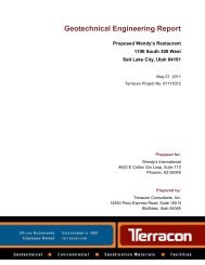
APPENDIX A - GEOTECHNICAL REPORT Th
- Page 770:
! ! ! ! ! ! ! ! ! ! ! ! ! ! GEOTECH
- Page 773 and 774:
! APPENDIX A ! "#$#%#&'!()*! +,-./0
- Page 775 and 776:
!"#$"%&'(%)*+,'-('"".('-+/"0#.$+ 1"
- Page 777 and 778:
!"#$"%&'(%)*+,'-('"".('-+/"0#.$+ 1"
- Page 779 and 780:
!"#$"%&'(%)*+,'-('"".('-+/"0#.$+ 1"
- Page 781 and 782:
!"#$"%&'(%)*+,'-('"".('-+/"0#.$+ 1"
- Page 783 and 784:
!"#$"%&'(%)*+,'-('"".('-+/"0#.$+ 1"
- Page 785 and 786:
!"#$"%&'(%)*+,'-('"".('-+/"0#.$+ 1"
- Page 787 and 788:
! APPENDIX A Vicinity Map Site Plan
- Page 789 and 790:
B-1 Map provided by SL&A Architects
- Page 791 and 792:
PSI Job No.: 710-85060 Project: Pro
- Page 793 and 794:
PSI Job No.: 710-85060 Drilling Met
- Page 795 and 796:
PSI Job No.: 710-85060 Project: Pro