- Page 1 and 2:
Moteurs diesel POWERTECH ® 10,5 l
- Page 3 and 4:
Concessionnaires John Deere Du fait
- Page 5 and 6:
Moteurs 6105HF et 6125HF POWERTECH
- Page 7 and 8:
Moteurs 6105HRW et 6125HRW POWERTEC
- Page 9 and 10:
Moteur 6105ADW POWERTECH ® Vue cô
- Page 11 and 12:
Introduction Moteurs 6125 POWERTECH
- Page 13 and 14:
SECTION 01—Généralités Groupe
- Page 15 and 16:
Table des matières Page Groupe 000
- Page 17 and 18:
Manipulation des liquides inflammab
- Page 19 and 20:
ATTENTION: L’acide sulfurique con
- Page 21 and 22:
Précautions pour l’entretien de
- Page 23 and 24:
Sécurité de l’éclairage du lie
- Page 25 and 26:
Élimination correcte des déchets
- Page 27 and 28:
Désignation du modèle du moteur E
- Page 29 and 30:
Tableau des applications du moteur
- Page 31 and 32:
Carburant diesel Groupe 002 Carbura
- Page 33 and 34:
Pouvoir lubrifiant du carburant die
- Page 35 and 36:
Huile pour moteur diesel—Moteurs
- Page 37 and 38:
Prolongation de la périodicité d
- Page 39 and 40:
Graisse Utiliser le type de graisse
- Page 41 and 42:
IMPORTANT: N’utiliser aucun addit
- Page 43 and 44:
Carburants, lubrifiants et liquide
- Page 45 and 46:
Rinçage et entretien du circuit de
- Page 47 and 48:
Section 02 Réparation et réglages
- Page 49 and 50:
Table des matières Page Page Mesur
- Page 51 and 52:
Groupe 010 Guide de remise à neuf,
- Page 53 and 54:
Débranchement de la conduite d’a
- Page 55 and 56:
Guide de remise à neuf, rodage et
- Page 57 and 58:
Guide de remise à neuf, rodage et
- Page 59 and 60:
NOTE: Déposer le démarreur et le
- Page 61 and 62:
Guide de remise à neuf, rodage et
- Page 63 and 64:
Aérosol de 453 g (16 oz) PT506 •
- Page 65 and 66:
Guide de remise à neuf, rodage et
- Page 67 and 68:
Rodage du moteur Guide de remise à
- Page 69 and 70:
Vérification du circuit d’admiss
- Page 71 and 72:
Guide de remise à neuf, rodage et
- Page 73 and 74:
Guide de remise à neuf, rodage et
- Page 75 and 76:
Dépose et pose du cache-culbuteurs
- Page 77 and 78:
Remplacement du joint du cache-culb
- Page 79 and 80:
Culasse et soupapes IMPORTANT: Afin
- Page 81 and 82:
Culasse et soupapes 8. Régler la p
- Page 83 and 84:
Culasse et soupapes Valeur prescrit
- Page 85 and 86:
Culasse et soupapes IMPORTANT: Les
- Page 87 and 88:
• Voir DÉPOSE ET POSE DES INJECT
- Page 89 and 90:
• Voir DÉPOSE ET POSE DE LA POMP
- Page 91 and 92:
Diagnostic des défaillances du joi
- Page 93 and 94:
Culasse et soupapes Ordre d’inspe
- Page 95 and 96:
Désassemblage et inspection de l
- Page 97 and 98:
Culasse et soupapes Assemblage d’
- Page 99 and 100:
Inspection et mesure des ressorts d
- Page 101 and 102:
Nettoyage, inspection et mesure des
- Page 103 and 104:
Nettoyage et inspection de la culas
- Page 105 and 106:
Mesure de l’épaisseur de la cula
- Page 107 and 108:
Mesure du D.I. du guide de soupape
- Page 109 and 110:
Rodage des sièges de soupape Culas
- Page 111 and 112:
Mesure de l’alésage des sièges
- Page 113 and 114:
Culasse et soupapes IMPORTANT: Les
- Page 115 and 116:
Pose d’un manchon d’injecteur u
- Page 117 and 118:
NOTE: Avant de l’utiliser, inspec
- Page 119 and 120:
Remplacement des manchons d’injec
- Page 121 and 122:
6. Boucher les cavités de vidange
- Page 123 and 124:
13. Appliquer généreusement de la
- Page 125 and 126:
Pose du manchon d’injecteur 1. En
- Page 127 and 128:
9. Visser sans le serrer un écrou
- Page 129 and 130:
Culasse et soupapes Nettoyage et in
- Page 131 and 132:
Pose de la culasse Culasse et soupa
- Page 133 and 134:
Serrage par rotation des vis de la
- Page 135 and 136:
Culasse et soupapes IMPORTANT: Les
- Page 137 and 138: Serrage par rotation des vis de bri
- Page 139 and 140: Culasse et soupapes IMPORTANT: Insp
- Page 141 and 142: Culasse et soupapes Valeur prescrit
- Page 143 and 144: Dépose et pose de la plaque avant
- Page 145 and 146: Pose de la plaque avant Bloc-cylind
- Page 147 and 148: Bielles—Généralités Les ancien
- Page 149 and 150: IMPORTANT: Ne pas faire tourner le
- Page 151 and 152: 8. Tracer des repères sur les biel
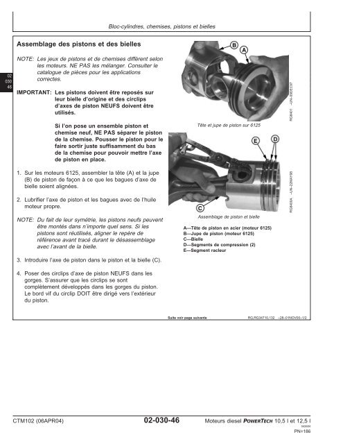
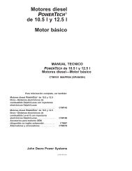
- Page 153 and 154: Bloc-cylindres, chemises, pistons e
- Page 155 and 156: Dépose des chemises de cylindre à
- Page 157 and 158: Inspection visuelle des chemises de
- Page 159 and 160: Bloc-cylindres, chemises, pistons e
- Page 161 and 162: Désassemblage de l’ensemble pist
- Page 163 and 164: Vérification de l’usure de la go
- Page 165 and 166: Vérification de l’usure de la go
- Page 167 and 168: Bloc-cylindres, chemises, pistons e
- Page 169 and 170: Mesure de l’épaisseur de la coll
- Page 171 and 172: Bloc-cylindres, chemises, pistons e
- Page 173 and 174: 3. Placer avec soin la bielle dans
- Page 175 and 176: Inspection des axes de piston et de
- Page 177 and 178: Dépose de la bague d’axe de pist
- Page 179 and 180: Désassemblage complet du bloc-cyli
- Page 181 and 182: NOTE: Le jeu d’entretien de chemi
- Page 183 and 184: Bloc-cylindres, chemises, pistons e
- Page 185 and 186: Pose des garnitures et joints toriq
- Page 187: Bloc-cylindres, chemises, pistons e
- Page 191 and 192: Bloc-cylindres, chemises, pistons e
- Page 193 and 194: 9. Tremper les vis et les rondelles
- Page 195 and 196: Vérification de la rotation du mot
- Page 197 and 198: Assemblage final NOTE: Se reporter
- Page 199 and 200: Ordre de serrage de l’amortisseur
- Page 201 and 202: Vérification du jeu axial du vileb
- Page 203 and 204: Vilebrequin, paliers et volant-mote
- Page 205 and 206: Vérification de l’ovalisation de
- Page 207 and 208: Inspection et réparation du volant
- Page 209 and 210: Dépose et pose du carter de volant
- Page 211 and 212: 3. Séparer le joint de son logemen
- Page 213 and 214: Analyse des défaillances du vilebr
- Page 215 and 216: 8. Fixer le marteau à coulisse D01
- Page 217 and 218: Dépose du vilebrequin 1. Déposer
- Page 219 and 220: Vilebrequin, paliers et volant-mote
- Page 221 and 222: Vilebrequin, paliers et volant-mote
- Page 223 and 224: Spécifications de rectification du
- Page 225 and 226: Inspection des paliers de butée V
- Page 227 and 228: Pose du vilebrequin Pose du palier
- Page 229 and 230: Pose du logement de joint d’huile
- Page 231 and 232: Pose du carter de distribution Vile
- Page 233 and 234: NOTE: Si l’entraînement de venti
- Page 235 and 236: Vilebrequin, paliers et volant-mote
- Page 237 and 238: 4. Mettre en place le pose-joint JD
- Page 239 and 240:
7. Poser la grande rondelle sur l
- Page 241 and 242:
Ordre de serrage du couvercle d’a
- Page 243 and 244:
Arbre à cames et train de pignons
- Page 245 and 246:
Réglage du jeu entre dents des pig
- Page 247 and 248:
Arbre à cames et train de pignons
- Page 249 and 250:
Arbre à cames et train de pignons
- Page 251 and 252:
4. Retirer le couvercle d’accès
- Page 253 and 254:
Arbre à cames et train de pignons
- Page 255 and 256:
6. Pousser l’arbre à cames vers
- Page 257 and 258:
9. Enlever l’outil de retenue d
- Page 259 and 260:
Remplacement de l’axe d’entraî
- Page 261 and 262:
Inspection du bossage du capteur de
- Page 263 and 264:
Poser le dépose-bague JDG968-1 dan
- Page 265 and 266:
10. Enlever le jeu d’outils et in
- Page 267 and 268:
Arbre à cames et train de pignons
- Page 269 and 270:
Entraînement auxiliaire arrière S
- Page 271 and 272:
Logement de filtre à huile et de c
- Page 273 and 274:
Dépose, inspection et pose du rég
- Page 275 and 276:
Dépose, inspection et pose de soup
- Page 277 and 278:
4. Retirer les deux grands écrous
- Page 279 and 280:
4. Mettre en place le logement filt
- Page 281 and 282:
5. Enlever le joint (B) entre la po
- Page 283 and 284:
Circuit de lubrification 4. Deuxiè
- Page 285 and 286:
Dépose et pose du tube de captage
- Page 287 and 288:
NOTE: Positionner l’arrière du c
- Page 289 and 290:
Remplacement des roulements dans l
- Page 291 and 292:
Circuit de refroidissement Vue écl
- Page 293 and 294:
Circuit de refroidissement Valeur p
- Page 295 and 296:
Remplacement du tendeur de courroie
- Page 297 and 298:
Nettoyage et inspection des pièces
- Page 299 and 300:
Circuit de refroidissement Valeur p
- Page 301 and 302:
Test de la température d’ouvertu
- Page 303 and 304:
Dépose et pose du chauffe-bloc—C
- Page 305 and 306:
Prolongement de la vie utile du tur
- Page 307 and 308:
Dépose du turbocompresseur ATTENTI
- Page 309 and 310:
DÉFAUTS À LA SORTIE DE L’ENVELO
- Page 311 and 312:
NOTE: Pour cette opération, il fau
- Page 313 and 314:
2. Rechercher les signes de frottem
- Page 315 and 316:
Essai sur banc du turbocompresseur
- Page 317 and 318:
Essai du dégagement de palier tran
- Page 319 and 320:
Prélubrification du turbocompresse
- Page 321 and 322:
Brancher la conduite d’entrée d
- Page 323 and 324:
Circuit d’admission et d’échap
- Page 325 and 326:
Dépose, inspection et pose du coll
- Page 327 and 328:
Dépose et pose du refroidisseur in
- Page 329 and 330:
Inspection et réparation du refroi
- Page 331 and 332:
Circuit de carburant NOTE: Les manu
- Page 333 and 334:
Dépose et pose de l’alternateur
- Page 335 and 336:
Section 03 Principes de fonctionnem
- Page 337 and 338:
Fonctionnement général du moteur
- Page 339 and 340:
Le culbuteur des injecteurs électr
- Page 341 and 342:
Fonctionnement du moteur de base A
- Page 343 and 344:
Fonctionnement du moteur de base CT
- Page 345 and 346:
Fonctionnement du moteur de base A
- Page 347 and 348:
Fonctionnement du moteur de base St
- Page 349 and 350:
Fonctionnement du turbocompresseur
- Page 351 and 352:
Table des matières Page Groupe 150
- Page 353 and 354:
À propos de cette section du manue
- Page 355 and 356:
2 Recherche de pression excessive d
- Page 357 and 358:
Diagnostics et essais observables 1
- Page 359 and 360:
Diagnostics et essais observables 1
- Page 361 and 362:
Essai au dynamomètre 1. Brancher l
- Page 363 and 364:
Vérification de la pression d’hu
- Page 365 and 366:
Vérification d’étanchéité du
- Page 367 and 368:
Essai sous pression du circuit de r
- Page 369 and 370:
Diagnostics et essais observables R
- Page 371 and 372:
Vérification de la pression du col
- Page 373 and 374:
Vérification d’étanchéité de
- Page 375 and 376:
Vérification de la synchronisation
- Page 377 and 378:
Vérification de la profondeur du c
- Page 379 and 380:
Section 05 Outils et autres fournit
- Page 381 and 382:
Guide de remise à neuf, rodage et
- Page 383 and 384:
Outils de réparation et autres fou
- Page 385 and 386:
Outils de réparation et autres fou
- Page 387 and 388:
Outils de réparation et autres fou
- Page 389 and 390:
Outils spéciaux pour bloc-cylindre
- Page 391 and 392:
Outils de réparation et autres fou
- Page 393 and 394:
Outils de réparation et autres fou
- Page 395 and 396:
Autres fournitures pour bloc-cylind
- Page 397 and 398:
Outils de réparation et autres fou
- Page 399 and 400:
Outils de réparation et autres fou
- Page 401 and 402:
Outils spéciaux pour arbre à came
- Page 403 and 404:
Outils de réparation et autres fou
- Page 405 and 406:
Outils spéciaux pour circuit de lu
- Page 407 and 408:
Outils spéciaux pour circuit de re
- Page 409 and 410:
Outils spéciaux pour circuit d’a
- Page 411 and 412:
Outils spéciaux pour diagnostics e
- Page 413 and 414:
Fabrication des outils Groupe 190 O
- Page 415 and 416:
Table des matières Page Groupe 200
- Page 417 and 418:
Caractéristiques générales des m
- Page 419 and 420:
Caractéristiques de réparation et
- Page 421 and 422:
Caractéristiques de réparation et
- Page 423 and 424:
Caractéristiques de réparation et
- Page 425 and 426:
Caractéristiques de réparation et
- Page 427 and 428:
Caractéristiques de réparation et
- Page 429 and 430:
Spécifications du vilebrequin, des
- Page 431 and 432:
Caractéristiques de réparation et
- Page 433 and 434:
Caractéristiques de réparation et
- Page 435 and 436:
Caractéristiques de réparation et
- Page 437 and 438:
Caractéristiques de réparation et
- Page 439 and 440:
Spécifications des circuits de dé
- Page 441 and 442:
Spécifications des diagnostics et
- Page 443 and 444:
Spécifications de diagnostic APPLI
- Page 445 and 446:
Spécifications de diagnostic APPLI
- Page 447 and 448:
Index Page Page A Pose des pistons
- Page 449 and 450:
Index Page Page Température du liq
- Page 451 and 452:
Index Page Page Pose ..............