- Page 3 and 4:
Congreso SAM/CONAMET 2009 Buenos Ai
- Page 5 and 6:
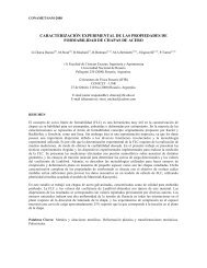
Luego del ensayo de nitruración, s
- Page 7 and 8:
a) Patrón b) N1 c) N2 d) Patrón e
- Page 9 and 10:
Congreso SAM/CONAMET 2009 Buenos Ai
- Page 11 and 12:
TCE Equiaxial TCE Columnar Potencio
- Page 13 and 14:
Los diagramas de impedancia obtenid
- Page 15 and 16:
Congreso SAM/CONAMET 2009 Buenos Ai
- Page 17 and 18:
El esquema cinético simplificado p
- Page 19 and 20:
La cinética de disolución indica
- Page 21 and 22:
Congreso SAM/CONAMET 2009 Buenos Ai
- Page 23 and 24:
E / V vs. SCE 4 3 2 1 0 0 200 400 6
- Page 25 and 26:
Cuando se aplica un potencial de 0.
- Page 27 and 28:
Congreso SAM/CONAMET 2009 Buenos Ai
- Page 29 and 30:
i/A cm -2 4.0x10 -5 2.0x10 -5 0.0 -
- Page 31 and 32:
REFERENCIAS El desarrollo de una p
- Page 33 and 34:
2. PROCEDIMIENTO EXPERIMENTAL Sorba
- Page 35 and 36:
Una forma de prevenir el biofouling
- Page 37 and 38:
Congreso SAM/CONAMET 2009 Buenos Ai
- Page 39 and 40:
Tabla 2. Composición de las mezcla
- Page 41 and 42:
especto al blanco y altos valores d
- Page 43 and 44:
Congreso SAM/CONAMET 2009 Buenos Ai
- Page 45 and 46:
estudiadas, respecto a las VC medid
- Page 47 and 48:
Teniendo en cuenta que a 250 rpm la
- Page 49 and 50:
Congreso SAM/CONAMET 2009 Buenos Ai
- Page 51 and 52:
de carga se hace circular el hidró
- Page 53 and 54:
partir de este gráfico se pudo obt
- Page 55 and 56:
Congreso SAM/CONAMET 2009 Buenos Ai
- Page 57 and 58:
i ( mA / cm² ) i ( mA / cm² ) i (
- Page 59 and 60:
4. CONCLUSIONES Los pretratamientos
- Page 61 and 62:
2. PROCEDIMIENTO EXPERIMENTAL Se tr
- Page 63 and 64:
Tabla 2. Tiempos de transición y p
- Page 65 and 66:
4. CONCLUSIONES Los espesores y la
- Page 67 and 68:
El efecto de la EPS provoca una pé
- Page 69 and 70:
3. RESULTADOS Y DISCUSIÓN Si bien
- Page 71 and 72:
humedad, son capaces de ampollar la
- Page 73 and 74:
CIM debido al agua presente en el s
- Page 75 and 76:
Figura 3. Fotografia del cupón de
- Page 77 and 78:
7. P.S. Guiamet, S.G Gómez de Sara
- Page 79 and 80:
Todos los especimenes fueron precal
- Page 81 and 82:
Figura 7: Probeta T670N, imagen de
- Page 83 and 84:
En el acero AISI 420, al aumentar l
- Page 85 and 86:
la corrosión en rendijas [9,10,11]
- Page 87 and 88:
Se observa que en todas las solucio
- Page 89 and 90:
ataque sufrido por medio de cloruro
- Page 91 and 92:
ealización de los ensayos electroq
- Page 93 and 94:
a) b) E (V) E (V) 1 0 -1 1E-7 1E-6
- Page 95 and 96:
4. CONCLUSIONES El sulfato es el a
- Page 97 and 98:
manteniéndose por debajo de las 40
- Page 99 and 100:
del mismo se distingue una sola con
- Page 101 and 102:
Congreso SAM/CONAMET 2009 Buenos Ai
- Page 103 and 104:
In this paper, the influence of ave
- Page 105 and 106:
The LOI test (ASTM D 2863) was carr
- Page 107 and 108:
Consequently, with the object of es
- Page 109 and 110:
hacen posible una alta adsorción d
- Page 111 and 112:
E ECS / mV 200 100 0 -100 -200 -300
- Page 113 and 114:
En la Tabla número 2, se aprecia l
- Page 115 and 116:
Congreso SAM/CONAMET 2009 Buenos Ai
- Page 117 and 118:
Congreso SAM/CONAMET 2009 Buenos Ai
- Page 119 and 120:
La reacción de los ácidos naftén
- Page 121 and 122:
Figura 2. Esquema de la planta de D
- Page 123 and 124:
4. CONCLUSIONES Se presentaron las
- Page 125 and 126:
2. PROCEDIMIENTO EXPERIMENTAL Las e
- Page 127 and 128:
El cronoamperograma en la presencia
- Page 129 and 130:
potencial inicial Ei= -0,65V. 1- ja
- Page 131 and 132:
presentan una mayor resistencia a l
- Page 133 and 134:
Las figuras 1 y 2, muestran que a 2
- Page 135 and 136:
Se observa que las corrientes de co
- Page 137 and 138:
observación metalográfica y DRX s
- Page 139 and 140:
En la Tabla 2 se reportan valores d
- Page 141 and 142:
Debe tenerse en cuenta que la expos
- Page 143 and 144:
Congreso SAM/CONAMET 2009 Buenos Ai
- Page 145 and 146:
Congreso SAM/CONAMET 2009 Buenos Ai
- Page 147 and 148:
Congreso SAM/CONAMET 2009 Buenos Ai
- Page 149 and 150:
trodo de trabajo (Aleación 22). Ad
- Page 151 and 152:
dancia, k es el factor de conversi
- Page 153 and 154:
4. CONCLUSIONES Mediante las técni
- Page 155 and 156:
Las características del recubrimie
- Page 157 and 158:
han reportado degradación de la mi
- Page 159 and 160:
la Tabla 3. Puede concluirse que la
- Page 161 and 162:
CONGRESO SAM/CONAMET 2009 BUENOS AI
- Page 163 and 164:
CONGRESO SAM/CONAMET 2009 BUENOS AI
- Page 165 and 166:
CONGRESO SAM/CONAMET 2009 BUENOS AI
- Page 167 and 168:
Si bien hay registros en la literat
- Page 169 and 170:
impronta en el microdurómetro fue
- Page 171 and 172:
el ensayo de erosión y se perdió
- Page 173 and 174:
Como electrolito se utilizó una so
- Page 175 and 176:
3-a) 3-b) Figura 3. a) Superficies
- Page 177 and 178:
En las caras pulidas mecánicamente
- Page 179 and 180:
Para cada tipo de enlace químico h
- Page 181 and 182:
Figura 1. Cambio de color. En la fi
- Page 183 and 184:
En la figura 5 y en la tabla 4 se m
- Page 185:
1032
- Page 188 and 189:
Figura 2. Esquema del reactor donde
- Page 190 and 191:
Figura 4. Evolución coordinación
- Page 192 and 193:
Congreso SAM/CONAMET 2009 Buenos Ai
- Page 194 and 195:
y 1 μ ≈ − EA − 2 ( IP + ) =
- Page 196 and 197:
En la tabla 2 se observa que el sis
- Page 198 and 199:
Congreso SAM/CONAMET 2009 Buenos Ai
- Page 200 and 201:
Microstructure is elucidated from t
- Page 202 and 203:
morphology observed by TOM. Bright
- Page 204 and 205:
Congreso SAM/CONAMET 2009 Buenos Ai
- Page 206 and 207:
donde, γ es la tensión superficia
- Page 208 and 209:
Se puede observar que con los térm
- Page 210 and 211:
Congreso SAM/CONAMET 2009 Buenos Ai
- Page 212 and 213:
parámetro ya que cuando la longitu
- Page 214 and 215:
Longitud de Fisura (mm) 3 2 1 0 Com
- Page 216 and 217:
Congreso SAM/CONAMET 2009 Buenos Ai
- Page 218 and 219:
3. Filtrando la matriz Isf se obtie
- Page 220 and 221:
información que dan los píxeles d
- Page 222 and 223:
Congreso SAM/CONAMET 2009 Buenos Ai
- Page 224 and 225:
las temperaturas Tξ´ asociadas a
- Page 226 and 227:
propuestas por Šesták y Berggren
- Page 228 and 229:
Congreso SAM/CONAMET 2009 Buenos Ai
- Page 230 and 231:
El haz fue polarizado linealmente e
- Page 232 and 233:
150ºC [5]. Dado que la experiencia
- Page 234 and 235:
Asimismo, y con el objetivo de aseg
- Page 236 and 237:
0.321 mm 0.319 mm 10/05 Figura 4. R
- Page 238 and 239:
2. PROCEDIMIENTO EXPERIMENTAL Se ex
- Page 240 and 241:
zona central). A tal fin se prepara
- Page 242 and 243:
constituidos fundamentalmente por M
- Page 244 and 245:
2. PROCEDIMIENTO EXPERIMENTAL El ma
- Page 246 and 247:
en la microestructura, lo cual reve
- Page 248 and 249:
5. G.D. De Almeida Soares, L.H. De
- Page 250 and 251:
2. PROCEDIMIENTO EXPERIMENTAL La es
- Page 252 and 253:
Dapp 40000 35000 30000 25000 20000
- Page 254 and 255:
REFERENCIAS 1. R. M. Torres Sanchez
- Page 256 and 257:
sodio (NaCl) al 3% p/v, durante 63
- Page 258 and 259:
Potencia /V Potencial /V 3,1E-02 3,
- Page 260 and 261:
4. CONCLUSIONES - El registro const
- Page 262 and 263:
eporta a nivel nacional en promedio
- Page 264 and 265:
El análisis de Difracción por ray
- Page 266 and 267:
incluidos en las interfases de los
- Page 268 and 269:
Cuando se somete el acero S32205 DS
- Page 270 and 271:
Figura 5. Posición del la lente ob
- Page 272 and 273:
1. Charles, J.; Superduplex stainle
- Page 274 and 275:
Las simulaciones de conformado del
- Page 276 and 277:
Ley 1 : h s ⎛ h ⎞ o γ = ho ⎜
- Page 278 and 279:
Figura 5. Diagrama de Límite de Co
- Page 280 and 281:
asándose en trabajos sobre otros m
- Page 282 and 283:
Figura 3: Espectros de DRX de los p
- Page 284 and 285:
Congreso SAM/CONAMET 2009 Buenos Ai
- Page 286 and 287:
La Figura 2 muestra los espectros M
- Page 288 and 289:
4. CONCLUSIONES La activación meca
- Page 290 and 291:
Congreso SAM/CONAMET 2009 Buenos Ai
- Page 292 and 293:
Congreso SAM/CONAMET 2009 Buenos Ai
- Page 294 and 295:
Congreso SAM/CONAMET 2009 Buenos Ai
- Page 296 and 297:
Con tal propósito, se decidió inv
- Page 298 and 299:
Figura 2. Superficie de cobre sin a
- Page 300 and 301:
AGRADECIMIENTOS El presente trabajo
- Page 302 and 303:
Además el MAV genera superficies d
- Page 304 and 305:
una de coordenadas. Finalmente, tom
- Page 306 and 307:
Por otra parte, las distribuciones
- Page 308 and 309:
formador de hidruro (MFH) reversibl
- Page 310 and 311:
(a) Figura 2: (a) Modelo simplifica
- Page 312 and 313:
entre punto y punto para que la tem
- Page 314 and 315:
Congreso SAM/CONAMET 2009 Buenos Ai
- Page 316 and 317:
Congreso SAM/CONAMET 2009 Buenos Ai
- Page 318 and 319:
Congreso SAM/CONAMET 2009 Buenos Ai
- Page 321 and 322:
Congreso SAM/CONAMET 2009 Buenos Ai
- Page 323 and 324:
3.2 Del sistema Cu-Sn Figura 1. Dia
- Page 325 and 326:
Tabla 1 : Modelos termodinámicos p
- Page 327 and 328:
Congreso SAM/CONAMET 2009 Buenos Ai
- Page 329 and 330:
saturación. Para el caso de rango
- Page 331 and 332:
eportada por Mateo y col. [10] que
- Page 333 and 334:
Congreso SAM/CONAMET 2009 Buenos Ai
- Page 335 and 336:
se estudiaron las fases hp6 y hp4,
- Page 337 and 338:
presentan comportamiento ferromagn
- Page 339 and 340:
Congreso SAM/CONAMET 2009 Buenos Ai
- Page 341 and 342:
320, 360, 400 y 600. Como segunda f
- Page 343 and 344:
la suave curvatura debido al efecto
- Page 345 and 346:
interacción Coulomb on-site [14-16
- Page 347 and 348:
La energía de adsorción del Ni so
- Page 349 and 350:
El cálculo de la energía de adsor
- Page 351 and 352:
Son muchas las razones que hacen de
- Page 353 and 354:
Ensayos con cambios en la velocidad
- Page 355 and 356:
velocidad de difusión de los átom
- Page 357 and 358:
cómo afecta cada adición ternaria
- Page 359 and 360:
Como las simulaciones MCAS implican
- Page 361 and 362:
REFERENCIAS 1. G. S. Firstov, J. Va
- Page 363 and 364:
esa restricción, y que sin cambiar
- Page 365 and 366:
Claramente, hay una cierta arbitrar
- Page 367 and 368:
5. CONCLUSIONES En este trabajo se
- Page 369 and 370:
centro del cluster (Figura 1 (a)).
- Page 371 and 372: que estamos trabajando con una mono
- Page 373 and 374: que a la distancia de 1.0 Å se for
- Page 375 and 376: (a) (b) (c) Figura 1. Diagrama de e
- Page 377 and 378: al acero luego de ser fundido (80 c
- Page 379 and 380: Congreso SAM/CONAMET 2009 Buenos Ai
- Page 381 and 382: 0.2. Las concentraciones para las c
- Page 383 and 384: Figura 5. Volumen de la celda (ZrxH
- Page 385 and 386: Congreso SAM/CONAMET 2009 Buenos Ai
- Page 387 and 388: σ = (R/V) . l0 . b0 ó σ . V/R =
- Page 389 and 390: calibrada. Para confirmar esta unif
- Page 391 and 392: Congreso SAM/CONAMET 2009 Buenos Ai
- Page 393 and 394: En la aleación, la magnitud de la
- Page 395 and 396: nula (es decir, el sistema fluctúa
- Page 397 and 398: Congreso SAM/CONAMET 2009 Buenos Ai
- Page 399 and 400: Tabla II Velocidad del barral Defor
- Page 401 and 402: Mn S grieta Microcavidades coalesci
- Page 403: 4. CONCLUSIONES Los resultados obte
- Page 406 and 407: CONUAR se encuentra en una etapa de
- Page 408 and 409: tubo con las características dimen
- Page 410 and 411: 5. AGRADECIMIENTOS Al personal de C
- Page 412 and 413: de aislantes eléctricos de uso nuc
- Page 414 and 415: Finalmente se puede concluir que, d
- Page 416 and 417: La metodología de hidruración ha
- Page 418 and 419: Figura 2. Micrografías de polvos d
- Page 420 and 421: irregularidades del meat reveladas
- Page 424 and 425: In order to determine the configura
- Page 426 and 427: Hvf, and migration energy, Hvm, and
- Page 428 and 429: la velocidad. Se empleó la emisió
- Page 430 and 431: morfológico de la misma, las lámi
- Page 432 and 433: a la transformación de la fase β
- Page 434 and 435: Durante la deformación a temperatu
- Page 436 and 437: 3. RESULTADOS Figura 3: Reactor RA1
- Page 438 and 439: particular, la precipitación de hi
- Page 440 and 441: La energía libre molar de Gibbs pa
- Page 442 and 443: 4. COEFICIENTES Y MOVILIDADES. En l
- Page 444 and 445: 6. CONCLUSIONES Este trabajo prelim
- Page 446 and 447: 2. PROCEDIMIENTO EXPERIMENTAL 2.1.
- Page 448 and 449: 3.3. Caracterización por análisis
- Page 450 and 451: APÉNDICE Cálculo de la densidad t
- Page 452 and 453: Cuando esto ocurre, la región de l
- Page 454 and 455: uno de los barridos obtenidos en un
- Page 456 and 457: 5. V. Popov, V. Khmelevsky, A. Luki
- Page 458 and 459: capacidad del sistema para aprender
- Page 460 and 461: Las energías de disociación, E y
- Page 462 and 463: 4. CONCLUSIONES Se han aplicado nue
- Page 464 and 465: enfatizando su aspecto probabilíst
- Page 466 and 467: embargo, el costo computacional rep
- Page 468 and 469: parámetros). Encontramos que, para
- Page 470 and 471: 2. PRESENTATION OF THE MODEL AND TH
- Page 472 and 473:
Table 2: Interface equilibrium conc
- Page 474 and 475:
element and/or impurities) for the
- Page 476 and 477:
mejor opción para ser usado en com
- Page 478 and 479:
D S C - 4 9 - 0 8 / C O L - U M o C
- Page 480 and 481:
Para el caso de los conjuntos TL-05
- Page 482 and 483:
corrosión. Por otra parte, el horm
- Page 484 and 485:
que 9, a incolora cuando el pH es m
- Page 486 and 487:
Potencial de corrosión (V CSE ) 0,
- Page 488 and 489:
“acondicionamiento”. Las matric
- Page 490 and 491:
Figura 2. Aspecto de las resinas ce
- Page 492 and 493:
4. CONCLUSIONES A partir de los res
- Page 494 and 495:
características diferentes. Por es
- Page 496 and 497:
3. MATERIALES La tabla 2 muestra el
- Page 498 and 499:
por lo cual su utilización requeri
- Page 500 and 501:
3. Templado beta del material forja
- Page 502 and 503:
Congreso SAM/CONAMET 2009 Buenos Ai
- Page 504 and 505:
En base a los resultados de los tub
- Page 506 and 507:
Para la observación con microscopi
- Page 508 and 509:
Los valores promedio del ancho de l
- Page 510 and 511:
Los resultados de la densidad de di
- Page 512 and 513:
2. PROCEDIMIENTO EXPERIMENTAL 2.1 E
- Page 514 and 515:
Tabla 1. Datos referentes al prepar
- Page 516 and 517:
Figura 8. Desplazamiento del brazo
- Page 518 and 519:
Se realizaron ensayos de inmersión
- Page 520 and 521:
óxido de color gris oscuro en las
- Page 522 and 523:
agua por 18 meses se contabilizaron
- Page 524 and 525:
2. PROCEDIMIENTO EXPERIMENTAL El po
- Page 526 and 527:
dg ( ) 14,0 12,0 10,0 8,0 6,0 4,0 2
- Page 528 and 529:
Obtuvimos una concordancia aceptabl
- Page 530 and 531:
the dumbbell is not the fundamenta
- Page 532 and 533:
Figure 2. Minimum energy 3I configu
- Page 534 and 535:
REFERENCES 1. D.J. Bacon, F. Gao, a
- Page 536 and 537:
la misma colada y su composición q
- Page 538 and 539:
La relación de Hall-Petch (H-P) [1
- Page 540 and 541:
Al seleccionar el TT utilizando est
- Page 542 and 543:
Figura 1. Esquema del circuito prim
- Page 544 and 545:
Tabla 1. Velocidad de corrosión de
- Page 546 and 547:
exposición. Además, para tiempos
- Page 548 and 549:
estima que el agregado de Zr y Nb a
- Page 550 and 551:
Se puede observar en la figura 2a q
- Page 552 and 553:
Con esta velocidad de enfriamiento,
- Page 554 and 555:
ecibe una fluencia (flujo neutróni
- Page 556 and 557:
En la cápsula de irradiación se u
- Page 558 and 559:
Figura 7: Probeta Charpy (1cm 2 de
- Page 560 and 561:
proceso es heterogéneo, comienza e
- Page 562 and 563:
Congreso SAM/CONAMET 2009 Buenos Ai
- Page 564 and 565:
• La aleación HYBRYD-BC1 present
- Page 566 and 567:
monocristal de ese mismo metal y P
- Page 568 and 569:
Pero de la figura se observa cómo
- Page 570 and 571:
f EL A EM5 A EL EL EL EL = 0, 115 ,
- Page 573 and 574:
Congreso SAM/CONAMET 2009 Buenos Ai
- Page 575 and 576:
and then tested for evaluation of m
- Page 577 and 578:
time. For coating treatment, C MOE
- Page 579 and 580:
Congreso SAM/CONAMET 2009 Buenos Ai
- Page 581 and 582:
Expansión (%) 0,200 0,180 0,160 0,
- Page 583 and 584:
Expansión (%) 0,350 0,300 0,250 0,
- Page 585 and 586:
Congreso SAM/CONAMET 2009 Buenos Ai
- Page 587 and 588:
Las muestras se mantuvieron durante
- Page 589 and 590:
asciende, observándose hasta 1000
- Page 591 and 592:
Congreso SAM/CONAMET 2009 Buenos Ai
- Page 593 and 594:
parámetros mencionados para los di
- Page 595 and 596:
extremas, de acuerdo al ángulo de
- Page 597 and 598:
Congreso SAM/CONAMET 2009 Buenos Ai
- Page 599 and 600:
ultra-rápida) se utilizó un susce
- Page 601 and 602:
almidón resultan, como consecuenci
- Page 603 and 604:
Congreso SAM/CONAMET 2009 Buenos Ai
- Page 605 and 606:
Congreso SAM/CONAMET 2009 Buenos Ai
- Page 607 and 608:
Congreso SAM/CONAMET 2009 Buenos Ai
- Page 609 and 610:
CUANTIFICACIÓN DE LA FASE NO CRIST
- Page 611 and 612:
agregado de estándar interno en ca
- Page 613 and 614:
3.2 Método del estándar interno:
- Page 615 and 616:
Congreso SAM/CONAMET 2009 Buenos Ai
- Page 617 and 618:
Congreso SAM/CONAMET 2009 Buenos Ai
- Page 619 and 620:
Congreso SAM/CONAMET 2009 Buenos Ai
- Page 621 and 622:
Congreso SAM/CONAMET 2009 Buenos Ai
- Page 623 and 624:
Figura 3. Comparación de curvas di
- Page 625 and 626:
Tabla 5. Análisis EDS y relación
- Page 627 and 628:
Congreso SAM/CONAMET 2009 Buenos Ai
- Page 629 and 630:
La curva dilatométrica del polvo d
- Page 631 and 632:
la temperatura de ablandamiento (TA
- Page 633 and 634:
RESUMEN: COMPORTAMIENTO MECÁNICO D
- Page 635 and 636:
% Al2O3 a % MgO a % C(s) a Fases pr
- Page 637 and 638:
σ F (MPa) 60 50 40 30 20 10 0 0,00
- Page 639 and 640:
Congreso SAM/CONAMET 2009 Buenos Ai
- Page 641 and 642:
En todos los espectros de rayos X d
- Page 643 and 644:
3.2 Reacciones químicas probables
- Page 645 and 646:
Congreso SAM/CONAMET 2009 Buenos Ai
- Page 647 and 648:
3. RESULTADOS Y DISCUSIÓN 3.1. Car
- Page 649 and 650:
Los productos compactos cocidos cor
- Page 651 and 652:
Congreso SAM/CONAMET 2009 Buenos Ai
- Page 653 and 654:
Densidad y porosidad. La porosidad
- Page 655 and 656:
Microscopía Electrónica. Análisi
- Page 657 and 658:
Congreso SAM/CONAMET 2009 Buenos Ai
- Page 659 and 660:
2. PROCEDIMIENTO EXPERIMENTAL 2.1 L
- Page 661 and 662:
por eso que la corrosión en el sen
- Page 663 and 664:
Congreso SAM/CONAMET 2009 Buenos Ai
- Page 665 and 666:
Se realizó un tratamiento térmico
- Page 667 and 668:
Los gases de alto horno también tr
- Page 669 and 670:
Congreso SAM/CONAMET 2009 Buenos Ai
- Page 671 and 672:
plasticity of both clays. The incor
- Page 673 and 674:
Diametral shrinkage (%) 4. CONCLUSI
- Page 675 and 676:
1523
- Page 677 and 678:
1525
- Page 679 and 680:
1527
- Page 681 and 682:
Congreso SAM/CONAMET 2009 Buenos Ai
- Page 683 and 684:
La observación de las muestras a m
- Page 685 and 686:
A partir de los 800 ºC, hasta 920
- Page 687 and 688:
Congreso SAM/CONAMET 2009 Buenos Ai
- Page 689 and 690:
La resistividad superficial de los
- Page 691 and 692:
corriente,Amp 1E-5 1E-6 1E-7 100 vo
- Page 693 and 694:
Congreso SAM/CONAMET 2009 Buenos Ai
- Page 695 and 696:
En la Figura 2 se presenta la varia
- Page 697 and 698:
Porosidad 1,0 0,8 0,6 0,4 1400 ºC
- Page 699 and 700:
Congreso SAM/CONAMET 2009 Buenos Ai
- Page 701 and 702:
3. RESULTADOS Y DISCUSIÓN 3.1 ANAL
- Page 703 and 704:
Intensidad (u.a) Cc80Ahid a 160ºC
- Page 705 and 706:
Congreso SAM/CONAMET 2009 Buenos Ai
- Page 707 and 708:
superior de óxidos de hierro en la
- Page 709 and 710:
similar al determinado para un prod
- Page 711:
Figura 8. Micrografías de la probe
- Page 714 and 715:
2. MATERIALES Y METODOS El PE usado
- Page 716 and 717:
Los resultados de la caracterizaci
- Page 718 and 719:
Congreso SAM/CONAMET 2009 Buenos Ai
- Page 720 and 721:
Soluciones de 0.5; 1; 2 y 4 ppm (mg
- Page 722 and 723:
plasma humano sobre una superficie
- Page 724 and 725:
Congreso SAM/CONAMET 2009 Buenos Ai
- Page 726 and 727:
σ máx [MPa] ε máx [%] w [x10 8
- Page 728 and 729:
En la Figura 6 se presenta la fotog
- Page 730 and 731:
Congreso SAM/CONAMET 2009 Buenos Ai
- Page 732 and 733:
Figura 2. Vista superior de la prob
- Page 734 and 735:
del compuesto. Es sabido que el má
- Page 736 and 737:
Congreso SAM/CONAMET 2009 Buenos Ai
- Page 738 and 739:
Los resultados de hinchamiento pued
- Page 740 and 741:
Existen en literatura evidencias qu
- Page 742 and 743:
Congreso SAM/CONAMET 2009 Buenos Ai
- Page 744 and 745:
Intensidad Intensidad (a) (c) MC 16
- Page 746 and 747:
comportamiento elástico. Sin embar
- Page 748 and 749:
Congreso SAM/CONAMET 2009 Buenos Ai
- Page 750 and 751:
Se realizaron ensayos mecánicos a
- Page 752 and 753:
3.3. Ensayo de fatiga La Figura 5 m
- Page 754 and 755:
Congreso SAM/CONAMET 2009 Buenos Ai
- Page 756 and 757:
Analizando la información reportad
- Page 758 and 759:
la derivada del ln β respecto a 1/
- Page 760 and 761:
Congreso SAM/CONAMET 2009 Buenos Ai
- Page 762 and 763:
donde DD corresponde al grado de de
- Page 764 and 765:
en las cápsulas de alginato-quitos
- Page 766 and 767:
Congreso SAM/CONAMET 2009 Buenos Ai
- Page 768 and 769:
OH N OH C NH NITRILO CETEN IMINO YN
- Page 770 and 771:
Figura 1. Curvas de tiempo-conversi
- Page 772 and 773:
Congreso SAM/CONAMET 2009 Buenos Ai
- Page 774 and 775:
El rodete que está elaborado con p
- Page 776 and 777:
Figura 5. Sujeción de dos álabes,
- Page 778 and 779:
Congreso SAM/CONAMET 2009 Buenos Ai
- Page 780 and 781:
Para estudiar la capacidad de absor
- Page 782 and 783:
% Abs /gr de gel 1000 500 0 -500 -1
- Page 784 and 785:
Congreso SAM/CONAMET 2009 Buenos Ai
- Page 786 and 787:
Congreso SAM/CONAMET 2009 Buenos Ai
- Page 788 and 789:
Congreso SAM/CONAMET 2009 Buenos Ai
- Page 790 and 791:
Congreso SAM/CONAMET 2009 Buenos Ai
- Page 792 and 793:
Congreso SAM/CONAMET 2009 Buenos Ai
- Page 794 and 795:
Congreso SAM/CONAMET 2009 Buenos Ai